
Correct driveshaft balance keeps rotating mass centered on the axis of rotation, which cuts vibration, slows wear on U-joints, bearings, and seals, and raises the shaft’s safe critical speed. Get it wrong and you’re not just living with a buzz in the seat. You’re feeding cyclic load into every drivetrain component downstream, and eventually something gives. If you already feel a sustained vibration at highway speed, back off that speed and get the shaft inspected before you drive it further.
- Balance affects three things directly: NVH (noise, vibration, harshness), component fatigue life, and the RPM ceiling before the shaft enters critical speed.
- A shop that performs proper dynamic balancing corrects imbalance across the shaft’s full length, not just at one point.
- Ozkonic Kustomz sees the same pattern across trucks that get lifted, towed hard, or run big tires: balance problems show up as “normal wear” long before anyone diagnoses them correctly.
Key Takeaways
Correct driveshaft balance reduces vibration, extends the service life of U-joints and bearings, and raises the shaft’s safe critical speed, and ignoring a sustained highway vibration risks compounding damage to the transmission and differential.
| Point | Details |
|---|---|
| Balance affects three systems | Vibration, component fatigue, and safe critical speed all shift when a shaft goes out of balance. |
| Watch for speed-linked vibration | Shimmy that scales with speed but not steering input usually points to the driveshaft, not the tires. |
| Dynamic balancing beats static | Multi-plane correction on a shop balancer handles modern two-piece and performance shafts better than single-point fixes. |
| Modifications change the math | Lifts, longer shafts, and diameter swaps lower critical speed and require a fresh balance check every time. |
| Replacement parts matter | Ozkonic Kustomz supplies vetted yokes, U-joints, and center bearings with fitment support when balancing alone won’t solve a worn or damaged component. |
A practical note from Ozkonic Kustomz
Balance problems hide in plain sight until they’ve already cost you a bearing or a transmission seal. Treat vibration as a diagnosis to chase down, not a quirk to live with, and when a worn part needs replacing, source it from someone who guarantees it’ll actually fit.
— Ozkonic Kustomz
Table of Contents
- Why the Role of Driveshaft Balance Matters for NVH and Durability
- What Causes Driveshaft Imbalance in the First Place
- How Shops Measure and Correct Driveshaft Balance
- Signs of Driveshaft Imbalance and How to Diagnose Them
- What Technicians Watch For Beyond the Balancer
- How an Imbalanced Driveshaft Drains Fuel Efficiency and Wears Out Other Parts
- Types of Driveshaft Balancing Weights and How They’re Installed
- How Material and Design Choices Change Balancing Requirements
- When Balance Alone Isn’t Enough: Getting the Right Replacement Parts
- Sources
Why the Role of Driveshaft Balance Matters for NVH and Durability
An unbalanced driveshaft spins with its center of mass offset from its center of rotation. That offset creates centrifugal force, and that force scales with the square of RPM. Double your shaft speed and the force from the same physical imbalance roughly quadruples. This is the mechanical reason a mild vibration at 45 mph turns into a violent shudder at 75.
That force doesn’t stay contained in the shaft. It travels through the U-joints, into the transmission’s output shaft, through the center support bearing if the truck has one, and into the differential pinion. Every one of those components was engineered for a specific load range, and cyclic force from imbalance adds fatigue cycles they weren’t designed to absorb.
Experimental studies on driveshaft balancing report vibration amplitude drops of roughly 40 to 60 percent in the resonance region after proper balancing, along with a critical speed increase of about 20 percent. Some vehicle-level testing also found cabin vibration at the seat point fell by about a third after balancing work.
That’s not a marginal gain. It’s the difference between a shaft that lives out its service life and one that’s slowly hammering itself apart.
- Imbalance forces get worse with speed, not linearly, but exponentially relative to RPM.
- The load doesn’t stop at the shaft. It propagates into U-joints, bearings, seals, and gearbox internals.
- A bad or imbalanced driveshaft can effectively “kinetically hammer” the transmission’s output components, leading to seal failure and bearing pitting over time.
- Parasitic loss from a fighting drivetrain also eats into power that should be reaching the wheels, a factor worth weighing alongside other horsepower upgrades under $500 that actually deliver measurable gains.
What Causes Driveshaft Imbalance in the First Place
Imbalance rarely announces itself. It accumulates from a handful of physical and system causes, most of which are easy to overlook during a routine inspection.
- Physical damage to the tube. A dent from a curb strike, a rock, or even careless jack placement shifts mass distribution enough to throw off balance, even when the dent looks cosmetic.
- Missing or displaced balance weights. Factory and aftershop balancing often uses small welded weights. If one falls off or a previous repair shop didn’t replace it correctly, the shaft is imbalanced again.
- Mud, rust, or undercoating buildup. Off-road trucks accumulate packed mud and corrosion on the shaft surface. That buildup adds uneven mass exactly where you don’t want it.
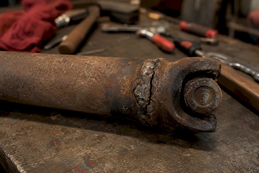
- Poor welding or amateur repairs. A shaft that’s been cut, shortened, or re-welded without a subsequent balance check almost always comes back imbalanced, even if the geometry looks fine by eye.
- Incorrect universal joint operating angles. Spicer’s installation guidance names U-joint angle as one of the three most common sources of driveline vibration, alongside imbalance and critical speed itself.
- Length or diameter changes from modifications. Lift kits, longer wheelbases, or diameter swaps change the shaft’s natural frequency, which lowers its critical speed even if static balance hasn’t changed at all.
Here’s the part that catches people off guard: a shaft can look perfectly straight, spin smoothly by hand, and still be dangerously close to its critical speed once you factor in the length and diameter changes from a lift or a longer bed swap. Visual inspection alone can’t catch that. Only spinning it at operating RPM, or running the numbers through a validated model, reveals the real risk.
How Shops Measure and Correct Driveshaft Balance
Static balancing corrects imbalance in a single plane, essentially treating the shaft like a wheel that needs weight added at one point around its circumference. It works for short, simple shafts but misses imbalance that’s distributed unevenly along the shaft’s length.
Dynamic balancing corrects imbalance across multiple planes simultaneously, which is what modern shafts on trucks, especially longer two-piece and slip-yoke designs, actually need. A shop balancer spins the shaft at controlled RPM, senses the imbalance electronically, and tells the technician exactly where and how much weight to add or remove.
A typical shop sequence looks like this:
- Inspect the shaft visually for dents, corrosion, and missing weights.
- Check runout with a dial indicator; target tolerance is typically under 0.002 inches.
- Mount the shaft on the balancer and spin it through a target RPM range.
- Add or remove correction weights based on the balancer’s readout.
- Verify U-joint phasing and operating angles before final approval.
RPM targets matter more than most owners realize. Factory shafts are commonly balanced around 3,000 to 3,500 rpm, which covers typical street driving. Performance and towing applications that see sustained higher shaft speeds should be balanced at 5,000 to 7,500 rpm to stay ahead of the vehicle’s real operating range. An analytical five-section beam model can calculate critical speed accurately enough to validate a design change without full finite element analysis, which is how engineers confirm a modified shaft still has margin before it hits resonance.
Pro Tip: A shaft that’s badly out of balance shouldn’t go straight to its target RPM on the balancer. Technicians typically pre-balance at a lower RPM first to avoid overloading the machine, then finish the correction at the intended operating speed.
Signs of Driveshaft Imbalance and How to Diagnose Them
Not every vibration comes from the driveshaft. Tires, wheel balance, and worn CV joints can mimic the same symptoms, so isolating the actual source saves you from paying for the wrong repair.
- Note when the vibration appears. A shimmy that scales with vehicle speed and barely changes with steering input points toward the driveshaft or wheels, not suspension bushings.
- Listen for a clunk on acceleration or deceleration. That usually means U-joint play or a loose slip yoke rather than pure imbalance.
- Check for a vibration that changes with engine load but not speed. That pattern often points to engine or motor mounts instead of the driveline.
- Do a visual walk-around. Look for dents, rust flaking, missing weights, and packed mud on the shaft tube.
- Grab the yokes and check for play. Excess movement at the U-joint signals wear that will throw off balance even if the shaft itself is straight.
- Inspect the center support bearing for cracking, looseness, or a dry rubber mount if the truck has a two-piece shaft.
Get it to a shop when the vibration is persistent at highway speed, when you spot visible tube damage, or after any major drivetrain modification, lift install, or a season of heavy towing. Those are the conditions most likely to push a shaft past what a quick eyeball check will reveal.
What Technicians Watch For Beyond the Balancer
Balancing fixes imbalance. It doesn’t fix a shaft that’s structurally compromised. Severe tube deformation, wall thinning from corrosion, or a cracked weld near the yoke means replacement is the safer call, no matter how clean the balancer readout looks afterward.
Street-driven trucks generally hold up fine with a balance check every couple of years or after any suspension work. Trucks used for towing or off-road duty should get checked more often, and any lift kit, gear swap, or shaft length change should trigger an immediate re-balance rather than waiting for symptoms.
A thorough shop pairs the balance correction with a runout check and a U-joint angle verification, since skipping the phasing check undermines otherwise correct balancing work. Sourcing yokes, center bearings, and U-joints from a vetted supplier matters here too. A poorly made replacement part can introduce new imbalance the moment it’s installed.
Pro Tip: If a shop tells you “it’s balanced now” but never checked U-joint angles or runout, ask them to redo it. A balanced shaft with the wrong operating angle will still vibrate.
How an Imbalanced Driveshaft Drains Fuel Efficiency and Wears Out Other Parts
A shaft fighting its own imbalance isn’t just noisy. It’s wasting energy that should be moving the truck forward. Every cycle of centrifugal force the engine has to overcome is parasitic load, energy converted to vibration and heat instead of forward motion. On a truck already losing power to drivetrain friction, that’s an avoidable drag on fuel economy that compounds at highway speed, exactly where imbalance forces are strongest.
The transmission usually absorbs the first hit. The output shaft bushing and seal sit right where that cyclic force enters the gearbox, and repeated hammering there leads to seal leaks, fluid loss, and eventually bearing wear inside the case itself. That’s an expensive repair to trace back to a $200 balance job that never happened.
The center support bearing, if the truck has a two-piece shaft, takes similar punishment. Its rubber isolator is designed for normal driveline flex, not sustained resonant vibration. Once that isolator starts breaking down, the bearing runs hotter and wears faster, and the vibration it was supposed to dampen starts transmitting straight into the frame.
U-joints wear unevenly under imbalance too, since the cyclic loading concentrates stress at specific points in the joint’s rotation rather than distributing it evenly. Differential pinion bearings and seals sit at the far end of that chain, and they’re often the last thing anyone suspects when a truck starts leaking gear oil for no obvious reason. If you’re chasing a drivetrain issue that seems to have no clear origin, an out-of-balance shaft belongs near the top of the suspect list, not the bottom.
Types of Driveshaft Balancing Weights and How They’re Installed
Correction weights come in a few standard forms, and the method a shop chooses depends on the shaft’s construction and how much correction it needs.
Clamp-on weights are the simplest option, small semicircular weights that bolt or clamp around the tube at the point the balancer identifies. They’re common on aluminum shafts where welding isn’t practical, since heat from welding can warp thin aluminum tube walls.
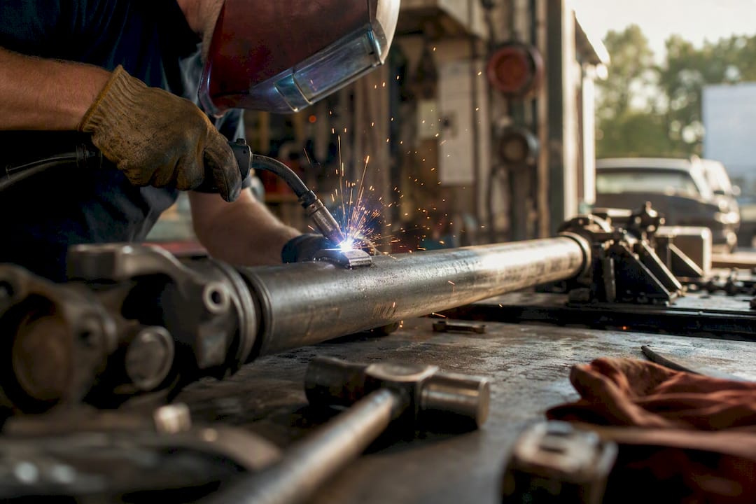
Weld-on weights are the standard for steel shafts. A technician tack-welds a small steel weight directly to the tube surface at the exact angular position and distance from center the balancer calculates. This is the most permanent and precise method, and it’s what most factory shafts use from the start.
Adhesive-bonded weights show up occasionally on lighter-duty applications where welding isn’t an option and clamping isn’t secure enough, though they’re less common in truck applications than the other two methods.
The installation sequence matters as much as the weight type. The balancer identifies both the angular position around the shaft and the amount of correction needed in ounce-inches. Get the position wrong by even a few degrees and the correction can make the imbalance worse instead of better, which is why this isn’t a job for guesswork with a torque wrench and a hunch. Old-school tricks like adding hose clamps or chalk marks to eyeball a fix are unreliable on anything beyond the slowest, shortest shafts, and shops generally advise against relying on them for modern multi-piece or high-speed applications.
How Material and Design Choices Change Balancing Requirements
Steel and aluminum shafts don’t behave the same way under rotation, and that difference shapes how they’re balanced. Steel is denser and stiffer for a given wall thickness, which generally gives it a lower natural frequency for the same length, meaning critical speed becomes a bigger concern on longer steel shafts. Aluminum is lighter, which raises the RPM ceiling before resonance becomes a problem, but its lower stiffness means it’s more sensitive to length and support point changes.
Carbon fiber shafts, increasingly common in performance builds, push critical speed even higher thanks to a favorable strength-to-weight ratio, but they demand tighter manufacturing tolerances since there’s less mass to “average out” small imperfections the way a heavier steel shaft naturally does.
One-piece versus two-piece design matters just as much as material. A two-piece shaft with a center support bearing effectively splits the rotating mass into two shorter sections, each with its own critical speed that’s typically higher than what a single long shaft of the same overall length would have. That’s part of why long-wheelbase trucks often run two-piece configurations instead of one continuous shaft.
Diameter plays a role too. A larger-diameter tube is stiffer for the same wall thickness, which raises critical speed, but it also means the balancer has to account for more surface area and mass distribution when calculating correction points. Any modification that changes length, diameter, or the number of support points, a lift kit, an axle swap, a longer bed conversion, changes the math on all of this, which is exactly why a axle shaft upgrade should always come with a fresh balance check rather than an assumption that the old numbers still apply.
When Balance Alone Isn’t Enough: Getting the Right Replacement Parts
Sometimes the shop finds more than an imbalance. A yoke with worn splines, a pitted center support bearing, or a U-joint with play no amount of correction weight will fix means you’re shopping for parts, and that’s where fitment problems usually start. A universal joint that’s technically the right size but built to loose tolerances will throw a freshly balanced shaft right back out of spec within a few thousand miles.

Ozkonic Kustomz sources yokes, U-joints, center support bearings, and the hardware around them directly from vetted manufacturers, so what shows up at your door actually fits the application it’s listed for. That’s a real advantage over combing through marketplace listings hoping the dimensions match your truck. Compare that to the trial-and-error most owners go through, ordering a part, finding out it’s close but not quite right, and shipping it back. Ozkonic Kustomz backs its parts with straightforward returns and support from people who understand driveline fitment, not just a warehouse pulling SKUs.
If you’re also rebuilding the harness or hardware around a drivetrain job, the modular wiring kit is a solid example of the fit-first approach applied elsewhere in the truck. Browse the current lineup or reach out for fitment help before you order, and get the right part the first time instead of guessing twice.
Sources
- Comprehensive study on driveshaft imbalance effects and balancing benefits
- Determination of critical speed for driveshafts (SAE paper)
- Driveshaft basics and balancing tips — Hot Rod
- Critical speed RPM calculator — Spicer Parts
- Engineerskill